I.S. Circuits - Loop Parameters
Published
Read Time: 2 mins
Entity Concept System
A common form of Intrinsically Safe system is the Entity Concept System (also called an Uncertified System – as the components of the system were not certified as a system or installation, with the compliance of the system relying on favourable Entity Parameter calculations).
At its most basic, an Intrinsically Safe circuit contains:
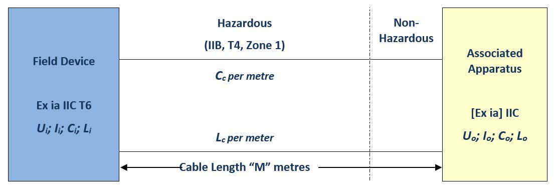
- Associated Apparatus (installed in the non-hazardous zone but with intrinsically safe outputs),
- a Field Device (such as a transmitter with intrinsically safe inputs – or an RTD which has no intrinsically safe parameters) and
- an Interconnecting Cable.
All of the above items have Parameters which must be matched correctly in order to maintain the Intrinsic Safety of the system.
Associated Apparatus
Examples of associated apparatus are:
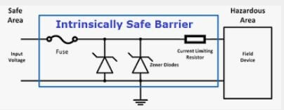
- Zener Barriers
- Intrinsically Safe Isolators
These devices have a standard electrical side which may withstand applied voltages of 250V – hence the common figure quoted as Um or Umax = 250V. This is defined as:
“The maximum voltage that can be applied to the non-intrinsically safe connection facilities of associated apparatus without invalidating the type of protection.” (AS/NZS 60079.11:2011 Clause 3.13.13).
These devices have Output Parameters, as follows:
- Uo – the maximum output voltage
- Io – the maximum output current
- Co – the maximum external capacitance that may be connected to the output of the device
- Lo – the maximum external inductance that may be connected to the output of the device
Intrinsically Safe (Field) Apparatus
Examples of Intrinsically Safe apparatus are:
- Pressure or Temperature Transmitters
- Level Transducers
- Proximity Detectors
These devices have Input Parameters, as follows:
- Ui – the maximum input voltage
- Ii – the maximum input current
- Ci – the maximum internal capacitance
- Li – the maximum internal inductance
Interconnecting Cable
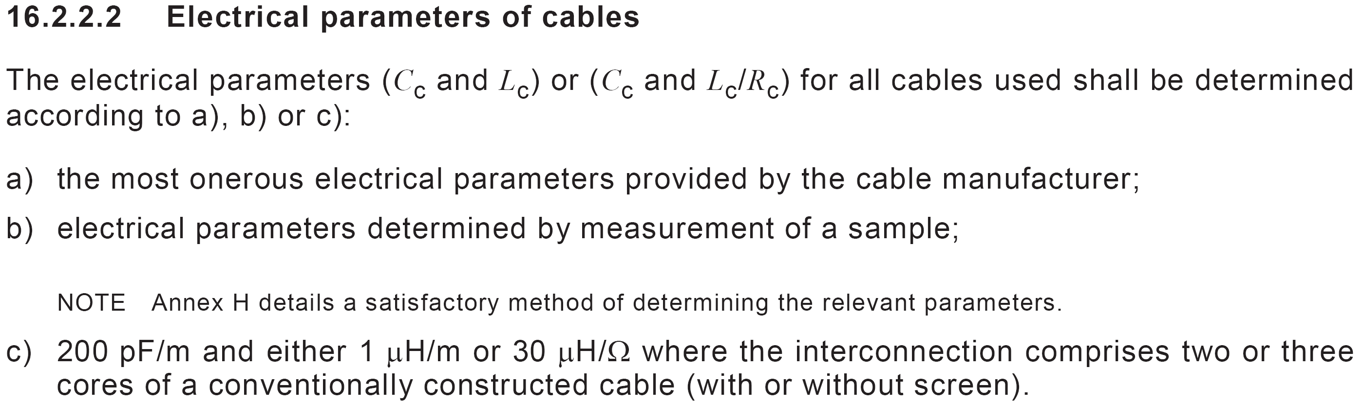
The cable which connects the associated apparatus in the non-hazardous (“safe area”) to the intrinsically safe field equipment, has its own parameters, available from the manufacturers cable data:
- Cc - Capacitance per unit length
- Lc - Inductance per unit length
If reliable data for the cable parameters cannot be found, the following alternate values may be used according to AS/NZS 60079.14:2017
Clause 16.2.2.2 (c):
Confirming Intrinsic Safety – Check of Loop Parameters
Is the Field Device Suitable for the Hazardous Area?
The Hazardous Area Classification for the area where the Field Device is installed is IIB, T4 and Zone 1. The field device is certified as Ex ia, IIC and T6.
- Ex ia equipment can be used in Zone 0, Zone 1 and Zone 2 – equipment is suitable on a Zone basis.
- IIC Equipment can be used in IIC, IIB and IIA hazardous areas – equipment is suitable on a Group basis
- The T6 Equipment can be used in a T1, T2, T3, T4, T5 and T6 hazardous areas – equipment is suitable on a Temperature Classification basis.
For this example, the answer is YES, it is suitable for the defined hazardous area.
Rules for Connecting the Field Device, Cable and Associated Apparatus
The following relationships must be true in order for the example intrinsically safe “loop” to be safe:
Ui > Uo Ii > Io Ci > Co+ [Cc x M] Li > Lo + [Lc x M]
This material is produced by HAZ. The information is of a general nature only and should not be relied upon. Each set of circumstances associated with compliance of hazardous areas and Type B compliance is unique and expert advice on your particular circumstances should be sought. HAZ accepts no liability for any reliance on the information published on this website.