Hazardous Area Classificaiton - AS/NZS 60079.10.1 VS API RP 505

Published
Read Time: 15 min
The focus of this technical paper is to perform a comparison of hazardous area classification using AS/NZS 60079.10.1 and API RP 505. These standards, and others, will be referred to, from time to time, throughout this paper:
- AS/NZS 60079.10.1:2009 (+A1) – Explosive atmospheres – Part 10.1: Classification of hazardous areas – Explosive gas atmospheres
- API RP 505 – Recommended Practice for Classification of Locations for Electrical Installations at Petroleum Facilities Classified as Class I Zone 0, Zone 1, and Zone 2 (API recommend practice 505, first edition, November 1997. Reaffirmed, August 2013).
- Model code of safe practice – Part 15 – Area classification for installations handling flammable fluids (EI-15) – 4th edition
- AS/NZS 3000:2018 – Electrical Installations “Wiring Rules”
Area Classification Objectives
AS/NZS 60079.10.1 Definition of Objectives
From AS/NZS 60079.10.1 Clause 4.2:
“Area classification is a method of analysing and classifying the environment where explosive gas atmospheres may occur so as to facilitate the proper selection and installation of equipment to be used safely in that environment. The classification also takes into account the ignition characteristics of the gas or vapour such as ignition energy (Group: e.g.: IIA, IIB or IIC) and ignition temperature (Temperature Class: e.g.: T1, T2, T3, T4, T5 or T6).”
Reference is then made to the requirement to select equipment appropriate to these defined areas of risk and lastly to the allocation of EPLs via a risk assessment process.
Where Hazardous Area Classification is Required by Law
Hazardous Area requirements are also stated in AS/NZS 3000, which is enacted at law under the Queensland Electricity Safety Act and Electrical Safety Regulation. Hazardous Area requirements are stated in AS/NZS 3000 Clause 7.7. In particular, regarding Hazardous Area Classification, the following is stated in Sub-clause 7.7.2.1:
“7.7.2.1 Responsibility for classification
The responsibility for classification of a hazardous area (as defined in AS/NZS 3000 Clause 1.4.15) rests with the persons or parties in control of the installation. The requirements are contained in AS/NZS 60079.10.1 for gas or vapour and AS/NZS 60079.10.2 for combustible dust.”
AS/NZS 3000 Clause 1.4.15 states as follows:
“1.4.15 Area, hazardous
Area in which an explosive atmosphere is present, or may be expected to be present, in quantities such as to require special precautions for the construction, installation and use of equipment [based on AS/NZS 60079 series].”
The above definition does not conflict with the intent of the definition in Section 2.1 of this technical paper.
Commonly Used Classification Standards in Australia
The following standards are used most commonly in Australia for the classification of flammable gas and vapour hazards:
- AS/NZS 60079.10.1 – which is called up directly or indirectly in most relevant legislation, as the mandatory or at least preferred Hazardous Area Classification standard for Flammable Gas and Vapour hazardous areas. However, this standard refers to both API RP 505 and EI-15 as “Normative” references, which in this case, means that these standards are compulsory to consider.
- API RP 505 – which is a commonly employed standard for larger plant, or for systems designed in Northern America which refers to Groups and Zones which are identical to the IEC meanings of these terms, and which may have been originally classified using API RP 500 which refers to Groups and Divisions as used in North America, rather than Groups and Zones.
- EI-15 (formerly referred to as IP-15) which is a Petroleum Industry Hazardous Area Classification standard from the United Kingdom, provides examples if classifications that AS/NZS 60079.10.1 does not identify except in general terms, for specific industries. This standard also contains excellent guidance on hazardous area classification methodology.
AS/NZS 60079.10.1
AS/NZS 60079.10.1:2009 (+A1) Explosive Atmospheres – Part 10.1 – Classification of areas – Explosive gas atmospheres describes two methods of hazardous area classification:
- Source of Release – Annex ZA (either by calculation or by example), and
- The Generalised Method – Annex ZB
Source of Release Method
A Source of Release is defined in AS/NZS 60079.10.1 Clause 3.9 as:
“a point or location from which a gas, vapour, mist or liquid may be released into the atmosphere so that an explosive gas atmosphere could be formed”
This is generally used for smaller installations, where the characteristics of the of the plant are well known. The Source of Release Method is defined in AS/NZS 60079.10.1 Clause 4.2 (paragraphs 5 & 6) as follows:
“The first step is to assess the likelihood of this, in accordance with the definitions of zone 0, zone 1 and zone 2. Once the likely frequency and duration of release (and hence the grade of release), the release rate, concentration, velocity, ventilation and other factors which affect the type and/or extent of the zone have been determined, there is then a firm basis on which to determine the likely presence of an explosive gas atmosphere in the surrounding areas.”
“This approach therefore requires detailed consideration to be given to each item of process equipment which contains a flammable material, and which could therefore be a source of release. This is the 'Source of Release Method'.”
This may be conducted using the equations in AS/NZS 60079.10.1 Annex A (not ZA) and calculating from first principles (also using guidance from further equations in Annex B (not ZB) and the worked examples in Section B.8 of that Annex). Alternatively, this method may be employed using the industry accepted solutions from AS/NZS 60079.10.1 in Annex ZA.
Generalised Method
AS/NZS 60079.10.1 Clause 5.4.7 and Annex ZB, refer to what is called the “Generalised Method” of classification. This is generally used for large plant before or even during the initial construction phase (example: a large LNG plant or a refinery). Note that refinements can be made by using a combination of Source of Release and Generalised Methods as the plant matures.
Clause 5.4.7 states:
“Where, through lack of detailed data or operating experience, it is not possible to identify and assess individual sources of release in a plant, a generalized method may be used.
Generalized methods require judgements to be made, usually for quite large sections of the plant, on whether the overall hazard is high (Zone 0 or Zone 1) or low (Zone 2). The judgement is best made by reference to a set of criteria based on industry experience and appropriate to the particular plant. The generalized method is that found in Annex ZB.
These generalized methods use broadly based zonal delineation and result in the following:
a) Large Zone 1 areas;
b) Large Zone 2 areas enclosing large Zone 1 areas.
Larger zone areas are characteristic of Generalized Methods, stemming from the ‘blanket’ type approach and the necessity to apply more conservative zonal classification where doubt exists as to the hazards involved. These methods can err on the side of safety but this may result in a more costly plant due to the additional quantity of explosion-protected equipment required. The ‘blanket’ type approach has the weakness of possibly missing Zone 1 areas within Zone 2 areas due to lack of specific recognition of individual sources of release.”
However, AS/NZS 60079.10.1 Clause 5.4.8 states:
“The use of either or both methods for classification of a plant at various stages of its development or for various parts of the plant may be appropriate.”
Pros and Cons of Each Method
Source of Release Method
Basically, the Source of Release Method will provide the following advantages:
- A more precise classification, limiting the hazardous areas to each particular source of release with extents and Zones that relate only to the conditions driving that particular release
- Each source is considered, rather than a blanket approach which may give rise to a more onerous classification.
- This method could possible reduce the equipment count in terms of certified hazardous area technology. Also, fewer hazardous area equipment items, means fewer hazardous area inspections.
However, the Source of Release method has the following disadvantages:
- Locating the individual sources of release requires a number of site visits, many photographs, time to align these with available P&ID (Piping and Instrumentation Drawings) and detailed inspections of the site. What is on the drawing may not be the way it was actually constructed. No accurate hazardous area classification can ever be compiled, without detailed site inspections by the classifier.
- Calculating the individual and later the combined effects of each source of release for a large plant will take a deal more time than using the Generalised Method, and generally requires sophisticated graphics software which will compile individual classifications into a three dimensional model for the entire plant.
- The technical can be prone to errors with the input data is incorrect, or the data is interpreted incorrectly.
Generalised Method
Basically, the Generalised Method will provide the following advantages:
- A faster development time to evolve a hazardous area classification, as the areas are blanketed as Zone 1 or Zone 2, encompassing many individual sources of release, with no need to identify each one. This will assist with reducing the lead time before commissioning the plant.
- A worst case scenario can be adopted for the Group and Temperature classification, say, Zone 1, Group IIB and Temperature Classification T4, which will be the common specification for all hazardous area equipment within that plant, except where an exception may be required (motors, IIC areas, etc).
However, this has a number of disadvantages:
- Items which would have been in a non-hazardous area under a Source of Release classification, may end up being in a hazardous area under the Generalised Method.
- The more items of equipment located in a defined hazardous area, means more hazardous area equipment has to be purchased.
- The more items of equipment located in a defined hazardous area, also means more hazardous are installation inspections (both initial and cyclic).
Summary
When comparing both methods, what you tend to gain with one, you lose with the other.
API RP 505
API RP 505 supports to use the Source of Release method as well. Section 6.2 Sources of Release states as follows:
“6.2 SOURCES OF RELEASE (IEC 79-10, MOD)
6.2.1 The basic elements for establishing the hazardous zone types are the identification of the source of release and the determination of the grade of release.
6.2.2 Since an explosive-gas atmosphere can exist only if a flammable gas or vapor is present with air, it is necessary to decide if any of these flammable materials can exist in the area concerned. Generally speaking, such gases and vapours (and flammable liquids and solids that may give rise to them) are contained within equipment and piping, which may or may not be totally enclosed. It is necessary to identify whereas release of flammables could occur from such equipment or piping.
6.2.3 Each item of process equipment should be considered as a potential source of release of flammable material. If the item cannot contain flammable material, it clearly will not necessitate a hazardous (classified) area around it. The same will apply if the item contains a flammable material but is not likely to release it into the atmosphere; sec Section 6.5.9.
If it is established that flammable material may be released into the atmosphere, it first is necessary to determine the grade of release in accordance with the definitions, by establishing the likely frequency and duration of the release. It should be recognised that the opening of parts of enclosed process systems (for example, during filter changing) also should be considered as sources of release when developing the area classification. By means of this procedure, each release will be graded either "continuous," "primary" or ''secondary."
Having established the grade of the release, it then is necessary to determine the release rate and other factors (including ventilation) that may influence the type and extent of the zone.”
While this appears to be true from the examples provided within the standard, a number of these examples align more closely with the Generalised Method examples in AS/NZS 60079.10.1 Annex ZB.
Why API RP 505 is Sometimes Used
North American companies are familiar and comfortable with the classifications stated in API RP 500, which uses the North American concepts of Divisions rather than Zones and is the preferred standard for larger plant designed in North America.
API RP 500 uses the North American system of Groups (A – Acetylene; B – Hydrogen; C – Ethylene and D – Methane – for surface, flammable vapour and gas industries) as well as their own system of Temperature Classification, which contains the usual T1 through to T6 definitions, and which are identical to IEC definitions, but also defines sub-classifications within these such as T3A, for example.
API RP 505 uses the IEC concepts of Zones (rather than Divisions), Groups and Temperature Classifications.
For a pre-existing plant design, classified to API RP 500, the conversion to a classification based on API RP 500 is comparatively simple, for an initial classification of the plant, and comparatively fast to generate.
Note that the use of Divisions (1 or 2) in API RP 500 only considers two levels of risk, Division 1 being higher than Division 2. IEC (and AS/NZS) uses Zones (0, 1 or 2) and considers three levels of risk. The North American Division 1 is said to encompass Zones 0 and 1, however, Division 1 equipment is not generally accepted for Zone 0 usage when performing conformity assessments for example.
Easier to Convert Classifications from Divisions to Zones
For plant that was designed in North America and was previously classified using the Divisions concept under API RP 500, the conversion to API RP 505 is generally easy as the below example demonstrates – refer to Figure 1:
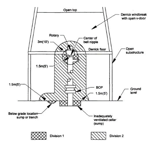
Figure 29 – API RP 500
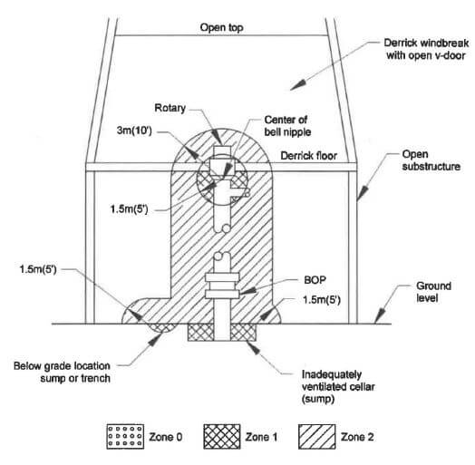
Figure 29 – API RP 505
Figure 1: Comparison of API RP 500 with API RP 505 Classification for a Drilling Well
The above is clearly a source of release type classification.
Further, it can be seen that when there are no Zone 0 areas to consider, the classifications in both API RP 500 and API RP 505 tend to be virtually identical.
AS/NZS 60079.10.1 Vs API RP 505
Source of Release Examples from both Standards
Example 1 - Floating Roof Tanks
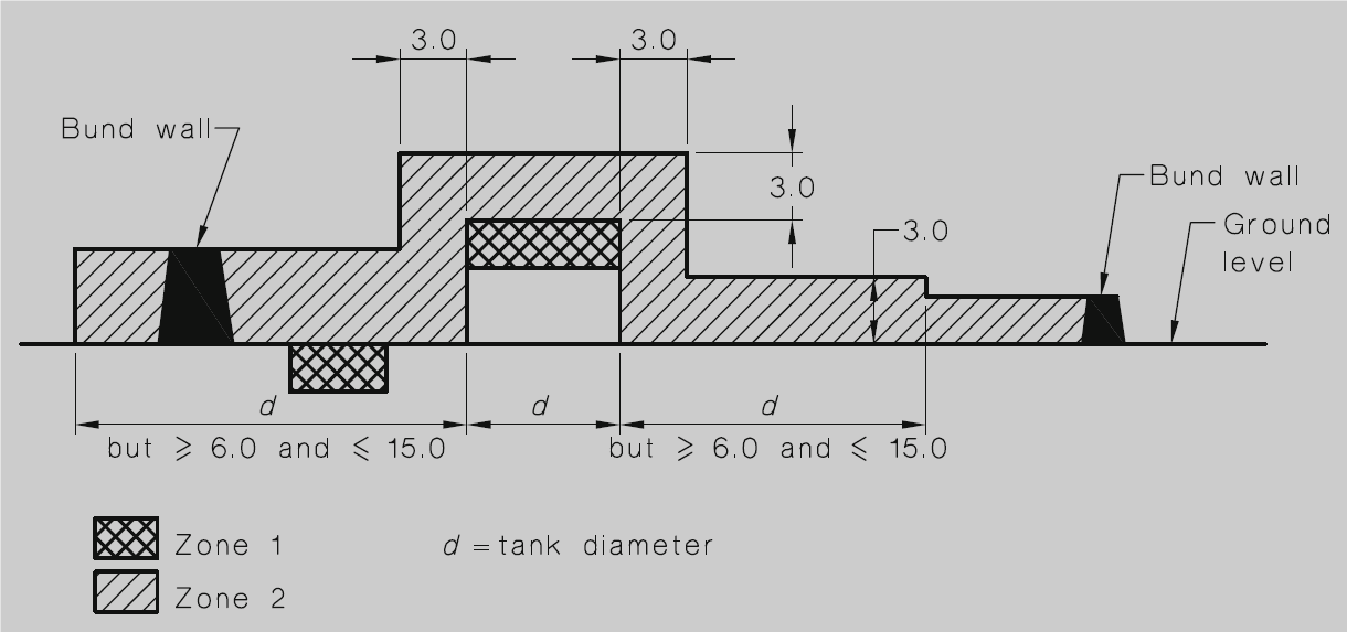
AS/NZS 60079.10.1 Figure ZA.26
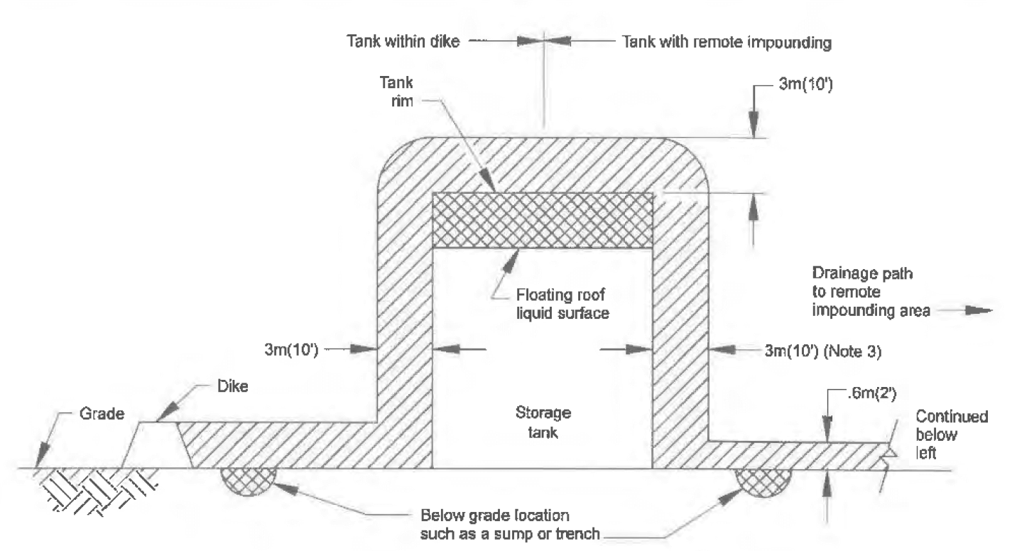 API RP 505
Figure 7 – Open Top Floating Roof Flammable Liquid Storage Tank
API RP 505
Figure 7 – Open Top Floating Roof Flammable Liquid Storage Tank
It can be seen that the classifications for both AS/NZS 60079.10.1 and API RP 505 for the same item, are almost identical. The difference is that AS/NZS 60079.10.1 has a bund and is classified to the height of that bund (definitely required in that instance) and has a bund on each side, whereas the API RP 505 figure has only on side bunded, with no bund height specified (though the Zone 2 area extends to the height of the bund as per AS/NZS 60079.10.1 Figure ZA.26).
The right hand side of API RP 505 Figure 7 has no bund and assumes the height of the Zone 2 area simply extends to a sump or bund wall downhill of the tank. In Australia, the entire tank would be bunded locally and the left hand side of this figure’s classification could be used on the right hand side of the figure to cover a complete bund.
Example 2 - Vents
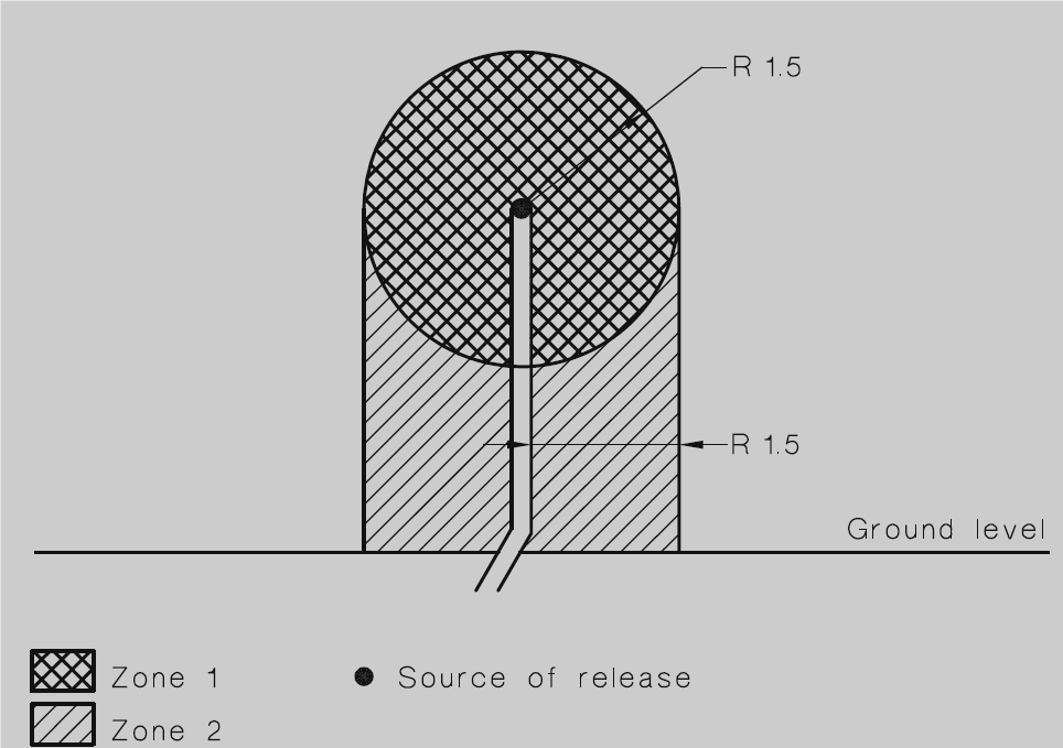
AS/NZS 60079.10.1 Figure ZA.30 – Vent Pipe Outlet:
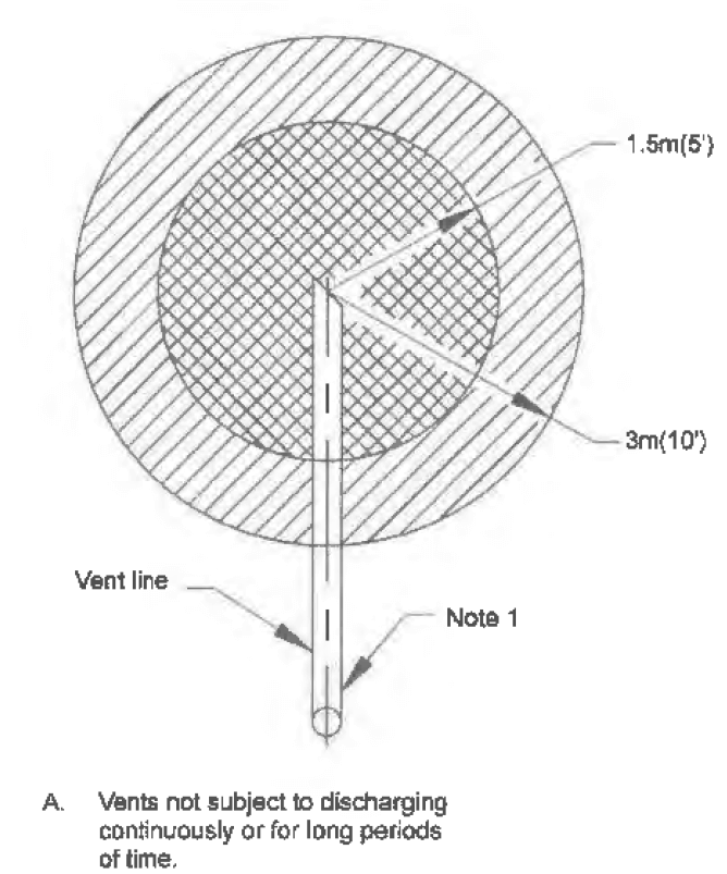
API RP 505 Figure 14A – Process Vent in an Non-enclosed Adequately Ventilated Area (not continuous discharge –
secondary source of release)
Differences:
AS/NZS 60070.10.1 Figure ZA.30: has no secondary Zone 2 area about the Zone 1 area around the entire Zone 1 area; but it does consider the possibility of a heavier than air gas or vapour. A lighter than air gas or vapour would classify more like API RP 505 Figure 14A.
API RP 505 Figure 14A: does not extend the Zone 2 area under the Zone 1 area to ground. This precludes a classification for heavier than air gases or vapours. A heavier than air gas or vapour would classify more like AS/NZS 60079.10.1 Figure ZA.30.
Generalised Method Examples – AS/NZS 60079.10.1 Annex ZB
Example 1 – Single Source of Release – Generalised Method
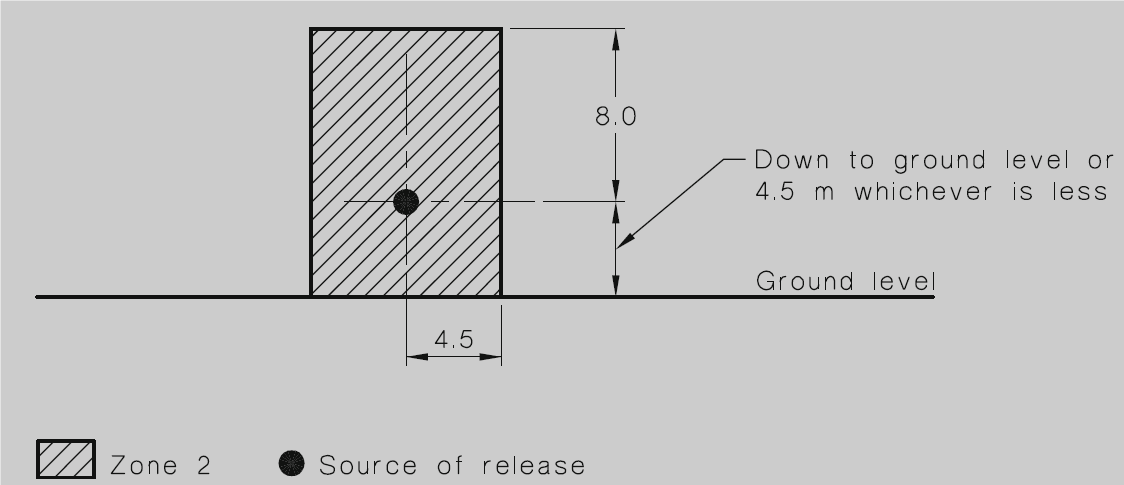
AS/NZS 60079.10.1 Figure ZB.5 – Adequately Ventilated Process Area – Lighter than Air Gas
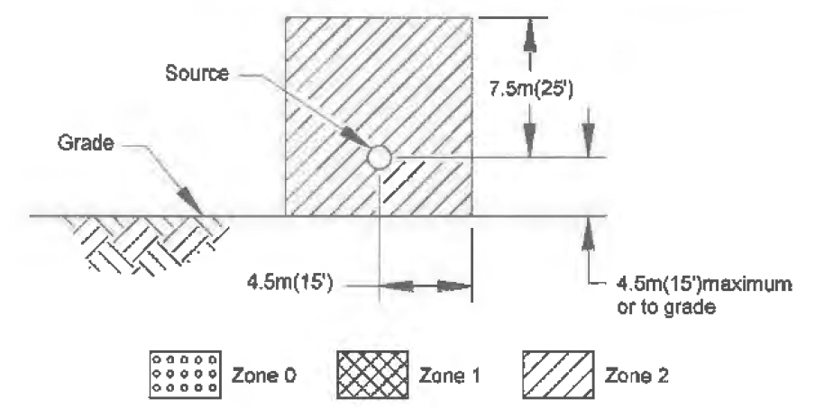
API RP 505 – Figure 24 – Adequately Ventilated Process Location – Lighter than Air Gas
From the above, it can be seen that the classifications are nearly identical. The AS/NZS 60079.10.1 classification is slightly more onerous by another 0.5 metres in height above the source.
Classifications Covered by API RP 505 and not Covered by AS/NZS 60079.10.1
There are a number of occupation specific classifications which are not considered by AS/NZS 60079.10.1 Annex ZA or Annex ZB. Particularly, these are for Drilling Rigs.
The following Figures from API RP 505 provide detailed classifications for Drilling Rigs which do not appear in AS/NZS 60079.10.1:
API RP 505 – Figure 29: Drilling Rig, Adequately Ventilated Substructure, Derrick not Enclosed
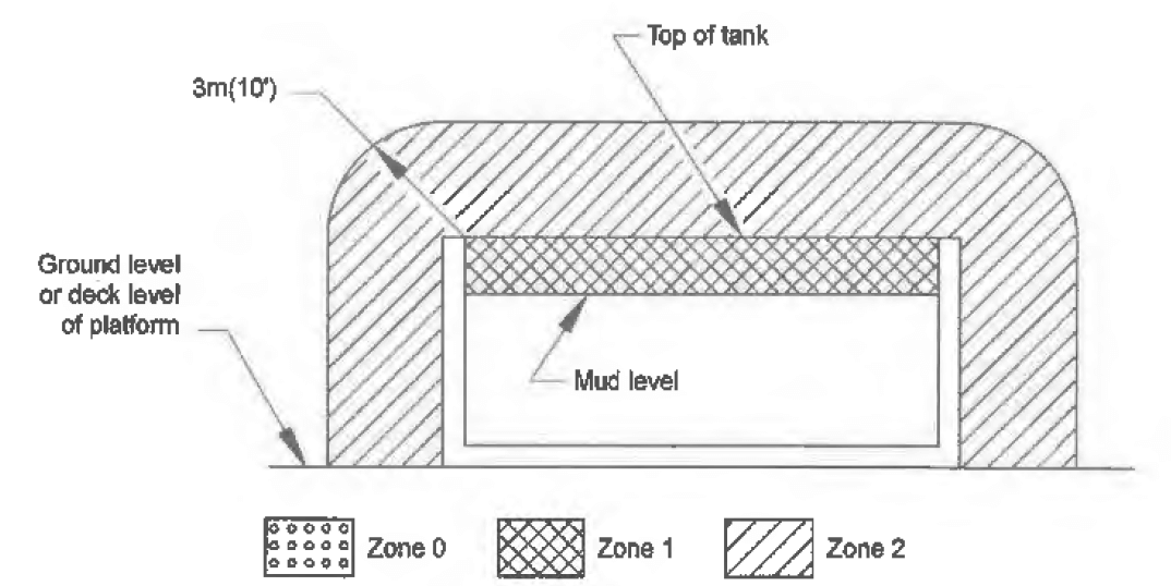
API RP 505 – Figure 33 – Mud Tank in a non-enclosed Adequately Ventilated Area
Summary
In summary, the following should be noted:
- AS/NZS 60079.10.1 refers to both API RP 505 and EI-15 as Normative References. That means that both of these standards must be considered as well as the requirements of AS/NZS 60079.10.1. Therefore, using API RP 505 to classify drill rig sites is completely proper and is in fact an inferred requirement.
- AS/NZS 60079.10.1 and API RP 505 have a large degree of commonality, when it comes to hazardous area classification solutions, albeit with some differences for very specific classifications.
- Section ZB – Generalised Method – and aspects of API RP 505 have nearly identical requirements and follow the same philosophy.
Conclusion
API RP 505 – 2013 is a fit for purpose hazardous area classification standard for drill rigs.
This material is produced by HAZ. The information is of a general nature only and should not be relied upon. Each set of
circumstances associated with compliance of hazardous
areas and Type
B compliance
is unique and expert advice on your particular circumstances should be sought. HAZ accepts no liability for any reliance on the
information published on this website.